Thursday, 31 March 2016

How to build Laptop Protector

Discription:

Protect your valuable laptop against theft using this miniature alarm generator. Fixed in-side the laptop case, it will sound a loud alarm when someone tries to take the laptop. This highly sensitive circuit uses a homemade tilt switch to activate the alarm through tilting of the laptop case. The circuit uses readily available components and can be assembled on a small piece of Vero board or a general-purpose PCB.
It is powered by a 12V miniature battery used in remote control devices. IC TLO71 (IC1) is used as a voltage comparator with a potential divider comprising R2 and R3 providing half supply voltage at the non-inverting input (pin 3) of IC1. The inverting input receives a higher voltage through a water-activated tilt switch only when the probes in the tilt switch make contact with water.
When the tilt switch is kept in the horizontal position, the inverting input of IC1 gets a higher voltage than its non-inverting input and the output remains low. IC CD4538 (IC2) is used as a monostable with timing elements R5 and C1. With the shown values, the output of IC2 remains low for a period of three minutes. CD4538 is a precision monostable multivibrator free from false triggering and is more reliable than the popular timer IC 555.
Circuit diagram
circuit diagram


Its output becomes high when power is switched on and it becomes low when the trigger input (pin 5) gets a low-to-high transition pulse. The unit is fixed inside the laptop case in horizontal position. In this position, water inside the tilt switch effectively shorts the contacts, so the output of IC1 remains low. The alarm generator remains silent in the standby mode as trigger pin 5 of IC2 is low.
When someone tries to take the laptop case, the unit takes the vertical position and the tilt switch breaks the electrical contact between the probes Immediately the output of IC1 becomes high and monostable IC2 is triggered. The low output from IC2 triggers the pnp transistor (T1) and the buzzer starts beeping. Assemble the circuit as compactly as possible so as to make the unit matchbox size.
Make the tilt switch using a small (2.5cm long and 1cm wide) plastic bottle with two stainless pins as contacts. Fill two-third of the bottle with water such that the contacts never make electrical path when the tilt switch is in vertical position. Make the bottle leak-proof with adhesive or wax. Fix the tilt switch inside the enclosure of the circuit in horizontal position.
Fit the unit inside the laptop case in horizontal position using adhesive. Use a miniature buzzer and a micro switch (S1) to make the gadget compact. Keep the laptop case in horizontal position and switch on the unit. Your laptop is now protected.


How to build Personal alarm

Circuit Diagram:

Personal alarm-Circuit diagram


PARTS:

  • R1 330K 1/4W Resistor
  • R2 100R 1/4W Resistor
  • C1 10nF 63V Polyester or Ceramic Capacitor
  • C2 100µF 25V Electrolytic Capacitor
  • Q1 BC547 45V 100mA NPN Transistor
  • Q2 BC327 45V 800mA PNP Transistor
  • SW1 Reed Switch and small magnet (See Notes)
  • SPKR 8 Ohm Loudspeaker (See Notes)
  • B1 3V Battery (two A or AA cells wired in series etc.)

Device Purpose:

This circuit, enclosed in a small plastic box, can be placed into a bag or handbag. A small magnet is placed close to the reed switch and connected to the hand or the clothes of the person carrying the bag by means of a tiny cord. If the bag is snatched abruptly, the magnet looses its contact with the reed switch, SW1 opens, the circuit starts oscillating and the loudspeaker emits a loud alarm sound. The device can be reverse connected, i.e. the box can be placed in a pocket and the cord connected to the bag. This device can be very useful in signalling the opening of a door or window: place the box on the frame and the magnet on the movable part in a way that magnet and reed switch are very close when the door or window is closed.

Circuit operation:

A complementary transistor-pair is wired as a high efficiency oscillator, directly driving a small loudspeaker. Low part-count and 3V battery supply enable a very compact construction.

Notes:

  • The loudspeaker can be any type, its dimensions are limited only by the box that will contain it.
  • An on-off switch is unnecessary because the stand-by current drawing is less than 20µA.
  • Current consumption when the alarm is sounding is about 100mA.
  • If the circuit is used as anti-bag-snatching, SW1 can be replaced by a 3.5mm mono Jack socket and the magnet by a 3.5mm. mono Jack plug with its internal leads shorted. The Jack plug will be connected with the tiny cord etc.
  • Do not supply this circuit with voltages exceeding 4.5V: it will not work and Q2 could be damaged. In any case a 3V supply is the best compromise.

How to build Ni -Cd Batteries Charger

Circuit Diagram

Ni -Cd Batteries Charger-Circuit diagram


Board Layout:


Ni -Cd Batteries Charger

parts use in it:

  • D1-4 = 1N4001
  • IC1 = 7808 (voltage regulator)
  • C1 = 1000uF/16V
  • C2 = 1uF/63V
  • IL1-4 = 6V/0,05A BULB
  • BH1-4 = AA BATTERY-HOLDER
  • F1 = 20mA FUSE + HOLDER
  • T1 = TRANSFORMER (10V/0,25A)

Cell Phone Detector circuit diagram and its work

The most common electronic equipment used is cell phones. With advancement in communication technology, the requirement of cell phones has increased manifold. A cell phone typically transmits and receives signals in the frequency range of 0.9 to 3GHz. This article provides a simple circuit to detect the presence of an activated cell phone by detecting these signals.

Basic Principle of Mobile Phone Detector Circuit:

The basic principle behind this circuit is the idea of using a Schottky diode to detect the cell phone signal. Mobile phone signal is in the frequency range of 0.9 to 3GHZ.  Schottky diodes have a unique property of being able to rectify low frequency signals, with low noise rate. When an inductor is placed near the RF signal source, it receives the signal through mutual induction. This signal is rectified by the Schottky diode. This low power signal can be amplified and used to power any indicator like an LED in this case.

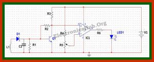
Circuit Diagram of Cell Phone Detector:Cell Phone Phone Detector Circuit Diagram

Circuit Components:
  • V1 = 12V
  • L1 = 10uH
  • R1 = 100Ohms
  • C1 = 100nF
  • R2 = 100K
  • R3 = 3K
  • Q1 = BC547
  • R4 = 200 Ohms
  • R5 = 100 Ohms
  • IC1= LM339
  • R6 = 10 Ohms
  • LED = Blue LED

Cell Phone Detector Circuit Design:

Detector Circuit Design:
The detector circuit consists of an inductor, diode, a capacitor and a resistor.  Here an inductor value of 10uH is chosen. A Schottky diode BAT54 is chosen as the detector diode, which can rectify low frequency AC signal. The filter capacitor chosen in a 100nF ceramic capacitor, used to filter out AC ripples. A load resistor of 100 Ohms is used.
Amplifier Circuit Design:
Here a simple BJT BC547 is used in common emitter mode. Since the output signal is of low value, the emitter resistor is not required in this case. The collector resistor value is determined by the value of battery voltage, collector emitter voltage and collector current. Now the battery voltage is chosen to be 12 V (since maximum open source collector emitter voltage for BC 547 is 45V), operating point collector emitter voltage is 5 V and collector current is 2 mA. This gives a collector resistor of approx 3 K. Thus a 3 K resistor is used as Rc. The input resistor is used to provide bias to the transistor and should be of larger value, so as to prevent the flow of maximum current. Here we chose a resistor value of 100 K.
Comparator circuit Design:
Here LM339 is used as comparator. The reference voltage is set at the inverting terminal using a potential divider arrangement. Since output voltage from the amplifier is quite low, the reference voltage is set low of the order of 4V. This is achieved by selecting a resistor of 200 Ohms and a potentiometer of 330 Ohms.  An output resistor of value 10 Ohms is used as a current limiting resistor.

Mobile Phone Tracking Circuit Operation:

In normal condition, when there is no RF signal, the voltage across the diode will be negligible. Even though this voltage is amplified by the transistor amplifier, yet the output voltage is less than the reference voltage, which is applied to the inverting terminal of the comparator. Since the voltage at non inverting terminal of the OPAMP is less than the voltage at the inverting terminal, the output of the OPAMP is low logic signal.
Now when a mobile phone is present near the signal, a voltage is induced in the choke and the signal is demodulated by the diode. This input voltage is amplified by the common emitter transistor. The output voltage is such that it is more than the reference output voltage. The output of the OPAMP is thus a logic high signal and the LED starts glowing, to indicate the presence of a mobile phone. The circuit has to be placed centimeters away from the object to be detected.Cell Phone Phone Detector Circuit Diagram

Cell Phone signal Jammer Circuit diagram

Mobile Jammer Circuit DiagramCell Phone Jammer Circuit Explanation:


  • If you understand the above circuit, this circuit analysis is simple and easy. For any jammer circuit, remember that there are three main important circuits. When they are combined together, the output of that circuit will work as a jammer. The three circuits are
    1. RF amplifier.
    2. Voltage controlled oscillator.
    3. Tuning circuit.
  • So the transistor Q1, capacitors C4 & C5 and resistor R1 constitute the RF amplifier circuit. This will amplify the signal generated by the tuned circuit. The amplification signal is given to the antenna through C6 capacitor. Capacitor C6 will remove the DC and allow only the AC signal which is transmitted in the air.
  • When the transistor Q1 is turned ON, the tuned circuit at the collector will get turned ON. The tuned circuit consists of capacitor C1 and inductor L1. This tuned circuit will act as an oscillator with zero resistance.
  • This oscillator or tuned circuit will produce the very high frequency with minimum damping. The both inductor and capacitor of tuned circuit will oscillate at its resonating frequency.
  • The tuned circuit operation is very simple and easy to understand. When the circuit gets ON, the voltage is stored by the capacitor according to its capacity. The main function of capacitor is to store electric energy. Once the capacitor is completely charged, it will allow the charge to flow through inductor. We know that inductor is used to store magnetic energy. When the current is flowing across the inductor, it will store the magnetic energy by this voltage across the capacitor and will get decreased, at some point complete magnetic energy is stored by inductor and the charge or voltage across the capacitor will be zero. The magnetic charge through the inductor will decreased and the current will charge the capacitor in opposite or reverse polarity manner. Again after some period of time, capacitor will get completely charged and magnetic energy across the inductor will be completely zero. Again the capacitor will give charge to the inductor and becomes zero. After some time, inductor will give charge to capacitor and become zero and they will oscillate and generate the frequency.
  • This circle run upto the internal resistance is generated and oscillations will get stop. RF amplifier feed is given through the capacitor C5 to the collector terminal before C6 for gain or like a boost signal to the tuned circuit signal. The capacitors C2 and C3 are used for generating the noise for the frequency generated by the tuned circuit. Capacitors C2 and C3 will generate the electronic pulses in some random fashion (technically called noise).
  • The feedback back or boost given by the RF amplifier, frequency generated by the tuned circuit, the noise signal generated by the capacitors C2 and C3 will be combined, amplified and transmitted to the air.
  • Cell phone works at the frequency of 450 MHz frequency. To block this 450MHz frequency, we also need to generate 450Mhz frequency with some noise which will act as simple blocking signal, because cell phone receiver will not be able to understand to which signal it has been received. By this, we can able to block the cell phone signal from reaching the cell phones.
  • So here in the above circuit, we generated the 450 MHz frequency to block the actual cell phone signal. That’s what the above circuit will act as a jammer for blocking the actual signal.

formate of cv

Text Box:  C.V

Muhammad HamzaBaig
S/o
AurangZaib
Vill. BurhanPur (Chuhan)
Tehsil & Post Office Pasrur District Sialkot,
Pakistan


Personal Information

Date & Place of Birth:                                                       June 21 1996 – Sialkot
Domicile:                                                                              Sialkot-Punjab
Citizenship #:                                                                      34602-0141959-1
Marital Status:                                                                    Single
Blood Group:                                                                       B + eve
Contact #:                                                                            0306-6629487
E-Mail:                                                                                   Hamzabaig1111@gmail.com

Objectives

My objective is to become a part of an organization which is dynamic & thriving among its competitors and get myself in a challenging position, an opportunity which not only enable me to fulfill my dream career but also to contribute toward achievement of organizational goals to prosperity and growth.
I have passion to work in teams which work together in stimulated environment through my dedication and loyalty to my assignments.

Profile

Well disciplined and positive attitude.


Academic Summary


  • Diploma of Associate Engineering                                                                 2013-2016

Government College of Technologies Sialkot
(Punjab Board of Technical Education Lahore)

  • Matriculation Certification                                                                    2012-2013

Marks in Metric’s Examination 743/1050                                     (A Grade)


Higher secondary school education in the field of Science from Govt. High School # 02Pasrur Sialkot (Board of Intermediate & Secondary Education Gujranwala)


Projects during Study:

·         Traffic light Controller
·         Laser Security system
·         LCD with Polarized goggles
·         Auto Water Level Project
·         Electrical Cycle
·         Solar tube well system


Achievements

Participate in Punjab Youth Festival and was a Leader of college team which participated in this Festival.

Participate three times in Project Exhibition in Govt. College of Technologies Sialkot and got award of best student.


Computer Literacy

·         Microsoft Word
·         Microsoft Excel
·         Microsoft Power Point
·         Internet and Email
·         Window installation


Interests

·         Reading Books
·         Playing Chess
·         Searching on technology
·         Playing football


wireless power transmiting systm

WIRELSS POWER TRANSMITTING SYSTEM:
                                                                                                                                          The project is a device to transfer power wirelessly instead of using conventional copper cables and current carrying wires. The concept of wireless power transfer was introduced by Nikolas Tesla. This power is made to be transferred within a small range only for example charging rechargeable batteries etc. For demonstration purposes we have used a fan instead of battery that operates by using wireless power. This requires an electronic circuit for conversion of AC 230V 50Hz to AC 12V, high frequency and this is then fed to a primary coil of an air core transformer. The secondary coil of the transformer develops 12V high frequency. Therefore by this way the power gets transferred through primary coil to secondary coil that are separated by certain distance around 3cm. Here the primary coil acts as transmitter and secondary coil receives the power to run a load. This project can be used to charge batteries of a pace maker and similar application

Hardware Specifications:
  • HF-Transformer
  • 2 Inductor Coils
  • Rectifier
  • Transistors
  • HF-diodes
  • DC Fan
  • Voltage regulator
  • LED’s

            BLOCK DIAGRAM OF WIRELESS POWER TRANSMITTING SYSTEM

Automatic 12v Battery Charger

This automatic battery charger circuit is mainly involves two sections – power supply section and load comparison section.
The main supply voltage 230V, 50Hz is connected to the primary winding of the center tapped transformer to step down the voltage to 15-0-15V.
The output of the transformer is connected to the Diodes D1, D2. Here diodes D1, D2 are used to convert low AC voltage to pulsating DC voltage. This process is also called as rectification. The pulsating DC voltage is applied to the 470uF capacitor to remove the AC ripples.
Thus the output of the capacitor unregulated Dc voltage. This unregulated DC voltage is now applied to the LM317 variable voltage regulator to provide regulated DC voltage.
The output voltage of this voltage regulator is variable from 1.2V to 37V and the maximum output current from this IC is 1.5A. The output voltage of this voltage regulator is varied by varying the pot 10k which is connected to the adjust pin of LM317.
Lm317 voltage regulator output is applied to the battery through the diode D5 and resistor R5. Here diode D5 is used to avoid the discharge of battery when main supply fails.
When battery charges fully, the zener diode D6 which connected in reverse bias conducts. Now base of BD139 NPN transistor gets the current through the zener so that the total current is grounded.
In this circuit green LED is used for indicating the charge of the battery. Resistor R3 is used to protect the green LED from high voltages.

Circuit Principle

If the battery voltage is below 12V, then the current from LM317 IC flows through the resistor R5 and diode D5 to the battery. At this time zener diode D6 will not conduct because battery takes all the current for charging.
When the battery voltage rises to 13.5V, the current flow to the battery stops and zener diode gets the sufficient breakdown voltage and it allows the current through it.
Now the base of the transistor gets the sufficient current to turn on so that the output current from LM317 voltage regulator is grounded through the transistor Q1. As a result Red LED indicates the full of charge.

Charger settings

The output voltage of the battery charger should be less than 1.5 times of the battery and the current of the charger should be 10% of the battery current. Battery charger should have over voltage protection, short circuit protection and reversed polarity protection.

Friday, 18 March 2016

water level indicater with circuitdiagram

Dancing Light using 555 Timer:

                                                                 A dancing light can be easily constructed using a 555 timer wired in astable mode. Please read the article Astable Multivibrator using 555 Timer before continuing. This circuit blinks two LEDs alternatively with some delay and it can be easily modified to include more LEDs or for controlling incandescent lamps. Time period of oscillation is determined by RC time constant of the circuit.

Circuit Diagram:

Dancing Light using 555 Timer - Circuit Diagram 
1st and 8th pins of 555 timer are used to provide power, Vcc and GND respectively. 4th is the Reset pin which is a active low input and is tide to Vcc to avoid accidental resets. 5th is the Control Voltage pin which is not used in this application, hence it is grounded via 0.01μF capacitor to avoid high frequency noises. When the output is HIGH capacitor charges to Vcc via resistor R1 and Diode. When the output is LOW capacitor discharges via resistor R2 and Discharge pin (7th) of 555 timer.
When the output is LOW (0V) upper LED glows and when the output is HIGH (5v)  lower LED glows. Instead of current limiting resistors R3, R4 you may use another LED, such that two LEDs will come in series. You can use higher supply voltages if you need to drive more LEDs. LM/NE555 can work upto 16V and SE555 can work upto 18V. 555 can source or sink up to 200mA current, if you need more current use a transistor driver. You can also connect this circuit to relay for controlling incandescent lamps as shown below.
Here transistor is wired as a switch, when the base input is HIGH transistor turns ON and the relay is energized. Since the output of the 555 timer is square wave, the relay energizes and de-energizes continuously. Incandescent lamps turns ON alternatively since they are connected to Normally Open (NO) and Normally Closed (NC) of the realy output.

LED ON – OFF period is determined by the resistors R1, R2 and the capacitor C1. You can change these resistors or capacitors to adjust the time period and can be determined by the equation, T = 1.1RC.
Since the capacitor charges through R1, charging time period,
Tcharging = THIGH = 1.1R1C1
Since the capacitor discharges through R2, discharging time period,
Tdischarging = TLOW = 1.1R2C1
Our 555 Astable Design Tool at the bottom of the article Astable Multivibrator using 555 Timer will make your calculations simpler.


how can i make a laser security system for home

Home security alarm system circuit diagram

Have you ever thought about implementing your own home security alarm systems? It’s one of the simplest and interesting circuits for electronic beginners. Our new home security equipment uses a LDR (Light Depended Resistor) to detect security problems. Theft attempt and other security threats can be controlled by using this simple circuit to improve your security systems. This is also best suited for school students for their high school project.
To implement this alarm system for home, you have to provide an optical path (with LASER beams) around your home. The LASER path is made possible with one LASER torch and 3 mirror arrangements which encloses the whole area. Please refer the project arrangement sectionbelow to make this optical (light) path. We have explained about home security system in detail with animation/ simulation.

Circuit diagram of Home security alarm:


 WORKING:
  • This circuit is based on LDR (Light Depended Resistor), a variable resistor in which the resistance varies according to the light intensity falling on it.
  • The LDR and resistor R1 forms a potential divider network, which is the main part of our security alarm circuit.
  • We have already discussed about how transistor act like a switch, the same principle is used here.
  • The voltage drop across the LDR is used to drive the transistor switch. When the voltage drop is above cut in voltage (0.6V), the transistor is turned ON.
  • LDR has low resistance (mΩ range) in the presence of light and high resistance (MΩ range) in the absence of light.
  • In our security alarm, a LASER light is allowed to fall on the LDR continuously using 3 mirrors (see the project arrangement figure).
  • Light from other sources should not be allowed to fall on the LDR, so place the LDR in a box with a single hole to pass LASER.
  • In this situation, the resistance offered by LDR is too low, since the LASER light is continuously allowed to fall on the LDR  surface.

  • Thus the voltage drop across the LDR is also low [V=IR (Ohm’s law)] which is insufficient to turn ON the transistor, so the transistor remains in OFF state.
  • When a person (eg: thief) makes a block to the continuous flow of LASER beam, then the light falling on the LDR gets blocked. Thus its resistance increases to a high value in the order of MΩ range (According to Ohm’s law V=IR).
  • While resistance increases the voltage drop also increases, when this voltage drop exceeds the cut in voltage of the silicon NPN transistor (0.6V; BC547), it will turn ON.
  • Then current from Vcc starts flowing to ground via the buzzer and transistor, which makes the beep sound.
  • The beep sound from the security alarm gives the indication of some security failures.

Simulation (animation) of the project

To realize the concept we are providing animation/ simulation of home security alarm circuit below. For animated demonstration, LED is used instead of buzzer.

how can i make a portable mobile charger by 9v battery


You can make your own portable mobile charger by 9v battery


BT1=battery connector
K1.1=switch
C1=100uf capacitor
U1=5v voltage regulator
D2= rectifying Diode
C2=220uf capacitor
R1=150ohm resistor
D1=led
R2=330ohm resistor
R3=10kohm resistor
Female usb port


Here is a list of things you need to build the Portable USB Power Supply
1-battery connector
1-switch
1-100uf capacitor
1-5v voltage regulator
1-rectifying Diode
1-220uf capacitor
1-150ohm resistor
1-led
1-330ohm resistor
1-10kohm resistor
1-female usb port
1-pcb board
1-9v battery
1-project box

 Female usb port points:


solder your compoent in this arrangement and enjoy your mobile batterylife if yoy want to make it at rechargable battery than you can change it by battery
its hap and casing becomes like that
 

Featured Post

All Answers of Quiz regarding to this course on Fiverr "Online Freelancing Essentials: Be A Successful Fiverr Seller"

To Clear All quiz of mentioned Course you can have a look on or check questions answers as well. Course name:  Online Freelancing Essentials...

Popular Posts